SysML = broad and richly expressive graphical language with aspects of system’s design: structure, behavior, requirements, parametrics (mathematical models)
SysML grammar and notations are defined by OMG (Object Management Group)
SysML is extension of UML and as such, some SysML rules are actually defined in UML specification document (ie ValueType is derivative of DataType)
Nine SysML diagrams:
– Block definition diagram (bdd)
– Internal block diagram (ibd)
– Use case diagram (uc)
– Activity diagram (act)
– Sequence Diagram (sd)
– State machine diagram (stm)
– Parametric diagram (par)
– Package diagram (req)
– Requirements diagram (pkg)
These 9 diagrams are categorized as follows:
– Behavior Diagram (dynamic change of system behavior over time)
– Structure Diagram (static system structure diagrams)
– Requirements Diagram

General Diagram Concepts
Frame = The diagram frame is mandatory. (must always be drawn out)
Contents area = region within
Header = has 4 parts:
– Diagram Kind (bdd)
– Model element type (package)
– Model element name (structure)
– Diagram name (dellsat-77)
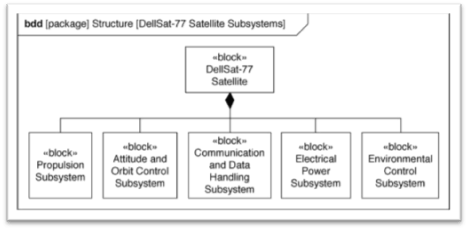
Diagram Kind = one of the nine SysML diagram types above.
Model element name and type represents the relationship to other parts of the system model hierarchy (in this example, this is part of the ‘structure package’) This acts as a namespace.

Two key points in regards to modeling and the diagrams:
- A diagram of the model is never the model itself; it is merely one view of it
- You cannot conclude that a feature doesn’t exist from its absence on a diagram; it may be shown on another diagram (or still exist even if not shown an any diagram)
SysML = general purpose graphical language that supports analysis, specifications, design, verification, and validation of complex systems.
[1] SysML can represent systems, components, and other entities such as:
– structural composition, interconnection and classification
– function-based, message-based and state-based behavior
– constraints on the physical and performance properties
– allocations between behavior, structure and constraints (eg. Functions allocated to components)
– requirements and their relationship to other requirements, design elements and test cases
SysML Diagram overview
[2,3,4,5,6,8,9,10,11]
Nine SysML diagram types:

- Requirement Diagram = text-based requirements and relationships to other requirements, design elements and test cases to support requirements traceability (not in UML)
- Activity Diagram = behavior in terms of actions, based on inputs/outputs/control, and how it forms input and outputs (modification of UML)
- Sequence Diagram = behavior in terms of messages exchanged between parts over time (same as UML)
- State Machine Diagram = behavior of an entity as it transitions between states by events (same as UML)
- Use Case Diagram = functionality in terms of how system / entity is used by external entities (actors) to accomplish some goal (same as UML)
- Block Definition Diagram = structural elements called blocks, and their composition and classification (modification of UML class diagrams)
- Internal Block Diagram = represents interconnection and interfaces between the parts of a block (modification of UML composite structure diagram)
- Parametric Diagram = represents constraints on property values (parameters), (not in UML)
- Package diagram = represents organization of a model in terms of packages that contain model elements (same as UML)
SysML and MBSE and examples
Use cases of the language may be: (study for exam pg 48)
– Capture and analyze black box system requirements
– Develop candidate system architectures to satisfy requirement
– Perform engineering and trade-off analysis to evaluate and select preferred architecture
– Specify component requirements and traceability to system requirements
– Verify that system design satisfies the requirements by executing system-level test cases
Definitions
Diagram frame = SysML diagram included
Diagram header = in diagram frame, top, description includes diagram name and context for digram content
Diagram content = content
Stereotype = user-defined notations (<<hardware>>, <<software>> etc)
Requirements Diagram relationships = derive, satisfy, verify, refine, trace and copy relationships
Block = very general modeling concept that has structure, such as systems, hardware, software, physical objects and abstract entities. Has a set of features that define its properties (eg weight), behavior in terms of activities allocated to the block or operations of the block, and interfaces defined by ports
Sequence Diagrams = use of lifelines, and the interaction between entities
Example of building car with fuel efficiency and performance:


