SysML language concepts are described in 3 parts:
– abstract syntax = or schema, described by metamodel
– concrete syntax = or notation, described by notation tables
– semantics = meaning

Architecture of SysML
There are 3 levels of concept relevant to modeling language:
– Domain concepts – the domain being modeled
– Mapping of domain concepts to language concepts
– Instantiation and representation of language concepts as they apply to particular system (eg block called car)
[1,2] Abstract syntax = schema and metatmodel
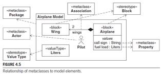
metamodel = describes the concepts in the language, their characteristics and interrelationships
[3] In metamodel, the individual concepts in a language are described by metaclasses that are related to each other using relationships such as generalizations and associations
MOF = Meta Object Facility = used to define UML and other metamodels


[4] Profile = mechanism used to customize the UML language, which contains stereotypes, used to extend the metaclasses in UML to create new or modified concepts in the customization. Figure 4.4 shows how UML4SysML is decomposed into SysML (block inherits from UML class, Value Type inherits from UML Data Type).
[5] Semantics = describe the meaning of its concepts in the domain of interest; via a mapping between the domain concepts and the language concepts.
System Model (or User Model) = description of a system and its environment for a specific purpose, such as validation of requirements for the system or to specific the system components. Consists of model elements that are instances of the metaclasses in metamodel.
[6] XMI = XML metadata interchange = data format used in UML models, including profiles like SysML, where the model can be translated in XML text. This XML file can be used to exchange models between modeling tools.
SysML Notations
[7] Notation = concrete syntax that describes how SysML concepts are visualized as graphical or textual elements. Detailed notation table found on page 535, example:

Diagram Frames
Every model must have diagram frame. Frame represents a model element that provides the context for the diagram context. It is a rectangle with header, or label, containing standard information on the top left corner. The rest is content area, or canvas.
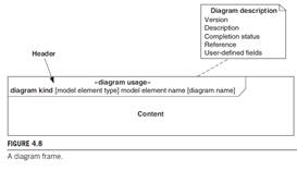
Diagram Header [8]
Diagram header (or label) is a rectangle with lower right corner cut off and includes the following
– Diagram kind (abbreviated)
o act, bdd, ibd, pkg, par, req, sd, stm, uc
– Model element type
o Used to remove ambiguity, but not necessary
o The valid types per diagram are:
- act = activity control operator
- bdd = block, constraint block, package, model, model library
- ibd = block
- pkg = package, model, model library, profile, view
- par = block, constraint block
- req = package, model, model library, requirement
- sd = interaction
- stm = state machine
- uc = package, model, model library
– Model element name = the name of the element
– Diagram name
o Intended to provide a concise description of diagram purpose only (since the model element name by itself may not be enough)
– Diagram usage = a keyword indicating a specialized use of a diagram, put in <<carrots>>
Diagram Description = optional note that attached inside or outside the diagram frame. Has predefined fields as well as user defined ones; the predefined ones are:
– Version
– Completion status
– Description
– Reference
Diagram Content = area or canvas, contains graphical elements that represent the underlying elements of the model. There are two types of graphical elements, nodes and paths.
[10] Properties and Keywords = keywords are in <<carrots>> (<<guillemets>>) and before the name of model element. Keyword identifies the type of model element (ie metaclass) and is typically used to remove ambiguity if there are similar graphical elements (eg rectangle, dashed arrow).
[9] Node Symbols, Path Symbols, Icon Symbols, Note Symbols are shown below


Additional Notations
Tables, Matrices, Trees – efficient and expressive ways of further representing information
