The most common SysML diagram is BDD, which includes elements such as blocks, actors, value types, constraint blocks, flow specifications and interfces.
Elements of Definition = the elements of a BDD, which are the foundation of everything else, contains the structural relationships, associations, generalizations and dependencies
BDD should be created often = created when stakeholder needs analysis, requirements definition, architectural design, performance analysis, test case development, integration
Bdd element types:
– Package
– Model
– modelLibrary
– View
– Block
– Constraintblock
Namespace = a model element that’s allowed to contain other model elements; can have other elements nested under it within the model hierarchy
Package = is the most common kind of namespace for various elements, it is named in the header of bdd and shows its relations to the model hierarchy
Example from above à The DellSat-77 bdd is from Structure package, and Structure package is the namespace for the elements shown in that bdd.
Blocks = basic unit of structure in SysML, any type of entity within the system or even external environment
Definition vs Instances:
Definitions = blocks, value types, constraint blocks; e.g. DesktopWorkstation
Instances = part properties, value properties constraint properties; e.g. SDX1205LJD:DesktopWorkstation
Structural Features
Structural Features = aka properties for a block:
– Part properties = the composures of a block (internals of the block)
– Reference properties = external dependencies to a block
– Value properties = represents quantity of some type
– Constraint Properties = mathematical relationship imposed on value properties
– Ports = distinct interactions external to block
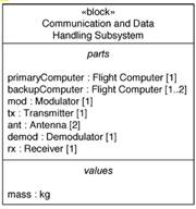
In this diagram, there are 7 parts to this block, each with types (primary Computer = part, Flight Computer = type). The number of types is controlled by part’s multiplicity, which defaults to 1.
Multiplicity of greater than 1 is called a collection of part instances (1 part of many instances)
Ownership = a part could be swapped out into different blocks (like an antenna) but at any given point in time, that part would have only a single owner
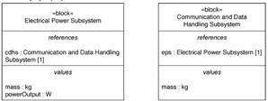
References are external to block, and not owned by the block, implies some connection necessary. References also carry type and multiplicity (cdhs is reference property and Comm & DH is type of default multiplicity of 1)
Value Properties are Boolean, string or numeric, also has multiplicity and default values (multiple types and instances). Some value properiest are assigned and others are derived / calculated. The calculated values are marked with (“/”) in front of property name.

Constraint properties represents the mathematical relationships (equation / inequality) for value properties. This gives higher level of fidelity. The constraint name is shown in block diagram but the constraint definition will appear in separate block diagram in the system model. A constraint block is special kind of block – one to encapsulate a reusable constraint expression. But it does not need to be in a separate constraint block, its just a best practice for reusability.


OR

OR
Ports represents interaction points to external entities which can interact with that structure, either to provide or request a service to exchange matter, energy or data. A block with port definitions makes it a black box to the other parts of the system, as it only needs to interact with the services provided by that block. It decouples the block’s clients from any internal implementation. This helps encapsulate blocks internal implementation and design to abstractions instead of specific implementations.
Standard port = interaction point with focus to services that a block provides or requires, defined by one or many interfaces. The interface is like a block, an element of definition, that defines set of operations and receptions. Required interfaces are marked with half circles on the block diagram whereas provided interface is a full circle.


Flow port = interaction point with focus on types of matter, energy or data that can flow in/out of block. Ports could be nonatomic (<>) to show it can have multiple types of items that flow in / out. Single flow ports are called atomic, shown below in 3.13. Flows specification blocks detail the flow properties, which include the direction, name and type. Flow direction can be in, out or inout. On the block diagram, a ~ tilde indicates the flow port is conjugated, or reverse the flow specifications.


Behavioral Features
Behavioral Features in block diagrams
– Operations = behavior that block performs when called (by some call event). Most commonly in synchronous behavior (meaning the caller waits for block to complete before commencing).
<operation name> (<parameter direction> <parameter name> : <parameter type> [multiplicity]) : <return type> [multiplicity]
Operations should have a verb phrase as part of its <operation name>.
– Receptions = behavior of block that performs when client sends a signal to trigger it. Invoked by signal event. Whereas an operation can by synchronous or asynchronous, a reception is always asynchronous (client never waits for block to finish after signaled). Also, a signal itself can be a model entity in its own block (reusable).


Reception must have same name as the signal. Can be in format:
<<signal>> <reception name> (<parameter name> : <parameter type> [multiplicity])
Associations
Associations – another notation for property
There are 3 main kinds of relationships between blocks:
- Associations
- Generalizations
- Dependencies
Associations are the reference property relationships (external to a block) and the part property relationship (internal to block).
Reference Association = solid line between two blocks, where an arrow represents unidirectional and no arrow represents bidirectional


The left diagrams show reference associations and reference properties separately. One could be used without the other, it depends on how much information is needed on the BDD.
Composite Association = structural decomposition between blocks. An instance of the block at the composite end is made up of some number of instances of the block at the part end.

Here the Dellsat is composed of 4 parts. The multiplicity at the composite end is restricted – a part can belong to only one composite at a time (0…1). Whereas on the part end, the multiplicity is unrestricted (1 or many, though here only shows 1). Sometimes composite association is used to expose the features of block with same part but different associations. (Flight Computer = part)

Generalizations = relationship that conveys inheritance between elements (a specializedsubtype from a generalizedsupertype). Used to create classification trees. Noted with solid line with hollow triangular arrowhead and referred to as “is a type of”. Each subtype block carries the same properties defined in its supertype (inherits). Note the second diagram below that shows more of an abstraction with association relationships also shown between the Flight Computer and Sensor.


This diagram shows that the sensor supertype has more than one subtypes for some of its parts.
Specialization = subtype of a supertype
Generalization = supertype of a subtype, these supertypes are used to create abstractions – where the model doesn’t show all the details of the subtypes
Dependencies = a relationship where the client depends on another element in the model, the supplier. When the supplier element changes, the client may change (whereas composite relationship it must change). These are used to establish traceability between elements. These often show up in package diagrams and requirements diagrams.

Actors
Actors = someone or something that has external interface with system, with a role convey in its definition. Can be displayed as a stick figure or by block with <<actor>> noted in it. Generally used in Use Case diagrams. There are two actor contraints:
- Cannot be defined as a generalization between actor and block
- Cannot have parts, other words – cannot be composite end of composite association.

Value Types
Value Types = element of definition that shows type of quantity, except for these two types:
– Boolean
– String
Usually part of value property in the structural feature of blocks. Generally 3 types for value types:
- Primitive
- Structured = has internal structure, generally two or more value properties; for example, SysML defines one structured value type: complex, which has two value properties for realPart and imaginaryPart
- Enumerated / enumeration = set of literals (legal values);</li

For the valueTypes VDC and VAC, they are using generalization relationships; the Real valueType is actually an abstraction, showing that a valueType hierarchy can be created.
Constraint Blocks
Constraint blocks = element of definition that must evaluate to true or false. Usually in constraint block, the expression is an equation or inequality; a mathematical relationship. This is noted in BDD with <<constraint>> preceding the constraint name. The constraint expression always appears between curly brackets {} in the constraints compartment of the constraint block.

This example shows a composite relationship of two simpler constraints composed together to form a larger complex constraint.
Comments
Comments = is a model element that consists of a single attribute, a string of text called the body. These are noted in a BDD with the note symbol / box (top right corner bent)

Comments can be linked (with line) or freestanding. Also, hyperlinks can be embedded as part of comments but this is not defined in SysML, just a feature found in some modeling tools.
There are 3 specialized kinds of comments in SysML: (these types are noted on the header of comments)
- Rationale
- Problem
- Diagram description